Difference between revisions of "Flip Flops"
(→Problems with basic (SR) flip flops) |
|||
| (2 intermediate revisions by the same user not shown) | |||
| Line 13: | Line 13: | ||
Basic flip flops are created using two NAND gates cross couples as seen in the image. | Basic flip flops are created using two NAND gates cross couples as seen in the image. | ||
| − | ==Problems with basic (SR) flip flops== | + | ===Problems with basic (SR) flip flops=== |
The downside of the SR Flip Flop is that if both Reset & Set are switched both Q and Not Q are on, which is not allowed. Also if both Reset & Set are changed at the same time from on to off (ie both on to both off) we cannot guarantee the output produced for Q. | The downside of the SR Flip Flop is that if both Reset & Set are switched both Q and Not Q are on, which is not allowed. Also if both Reset & Set are changed at the same time from on to off (ie both on to both off) we cannot guarantee the output produced for Q. | ||
| Line 20: | Line 20: | ||
| − | + | ||
| − | [[File:D-Type-ff.gif| | + | [[File:D-Type-ff.gif|300px|D type - Flip Flop]] |
This works however if the clock remains set, changes in Data will change the output Q. | This works however if the clock remains set, changes in Data will change the output Q. | ||
Latest revision as of 12:02, 24 January 2019
According to the specification you need to know what a Flip Flop is and that it is used to store a value. The specification specifically mentions the Edge Triggered D Type Flip Flop. You don’t need to know about the inner workings at all.
Contents
What is a flip flop
A flip-flop is used to store binary data, and is a simple latching circuit. When a value is set on the flip flop, the value is retained even when the input is switched off. This is how you can store a single bit of data in a computers memory.
https://www.youtube.com/watch?v=b0i1ShnNFKM&index=5&list=PLCiOXwirraUA9HyHoqOaGBU_k6nBRCb22
Basic (SR) Flip Flops
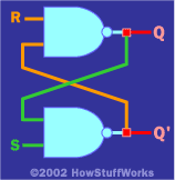
Basic flip flops are created using two NAND gates cross couples as seen in the image.
Problems with basic (SR) flip flops
The downside of the SR Flip Flop is that if both Reset & Set are switched both Q and Not Q are on, which is not allowed. Also if both Reset & Set are changed at the same time from on to off (ie both on to both off) we cannot guarantee the output produced for Q.
D and T type Flip Flops
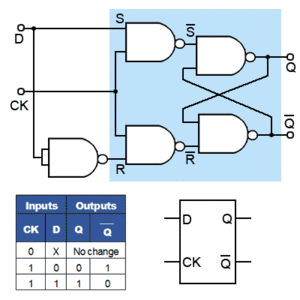
The issues of the SR flip flop are fixed with the so called Data flip-flop, this is able to ‘latch’ and remember data. It prevents both the indeterminate and non-allowed states of the SR flip-flop. The S and R inputs are now replaced by a single D input, and all D type flip-flops have a clock input.
This works however if the clock remains set, changes in Data will change the output Q.
Edge triggered D Type Flip Flop
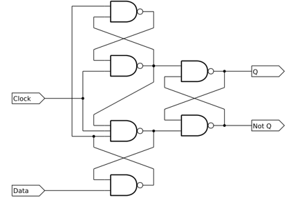
Now when you set the Data, and set the clock any changes in the data will not change the value of Q.
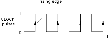
Each pulse of the system clock has a rising and falling edge. The edge triggered D type flip flop will change state on each pulse. For each pulse the data coming from the input will be stored until the next trigger pulse is received.


