Difference between revisions of "Flip Flops"
(→D and T type flippys) |
(→D and T type flippys) |
||
| Line 16: | Line 16: | ||
==D and T type flippys== | ==D and T type flippys== | ||
| − | A flip flop has two inputs. One input is a control input. For a D flip flop, the control input is labelled D. For a T flip flop, the control input is labelled T. The other input is a clock input, labelled either with a triangle or CK. | + | A flip flop has two inputs. One input is a control input. For a D flip flop, the control input is labelled D. For a T flip flop, the control input is labelled T. The other input is a clock input, labelled either with a triangle or CK. When a clock is drawn with a triangle like the ones below, these represent a positive-edge triggered clock, meaning that these can only change state when the clocks cycle is on a positive value i.e 1. When the clock is not on a positive value the bit stored within the flip flop is held i.e doesn't change. |
| + | |||
| + | |||
| + | |||
| + | |||
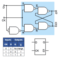
[[File:D-FlipFlop.png|200px]] [[File:D-FlipFlopLogic.png|200px|Logic circuit for a D-Flip Flop]] | [[File:D-FlipFlop.png|200px]] [[File:D-FlipFlopLogic.png|200px|Logic circuit for a D-Flip Flop]] | ||
[[File:T-FlipFlop.png|200px]] [[File:T-FlipFlopLogic.png|200px|Logic circuit for a T-Flip Flop]] | [[File:T-FlipFlop.png|200px]] [[File:T-FlipFlopLogic.png|200px|Logic circuit for a T-Flip Flop]] | ||
Revision as of 11:15, 16 March 2017
Contents
What is a flip flop
A flip-flop is used to store binary data, and is a simple latching circuit.
Basic (SR) Flip Flops
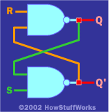
Basic flip flops are created using two NAND gates cross couples as seen in the image.
Problems with basic (SR) flip flops
Edge triggered D Type Flip Flop
D and T type flippys
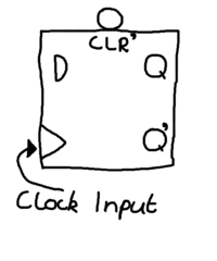
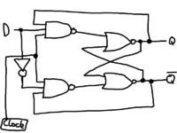
A flip flop has two inputs. One input is a control input. For a D flip flop, the control input is labelled D. For a T flip flop, the control input is labelled T. The other input is a clock input, labelled either with a triangle or CK. When a clock is drawn with a triangle like the ones below, these represent a positive-edge triggered clock, meaning that these can only change state when the clocks cycle is on a positive value i.e 1. When the clock is not on a positive value the bit stored within the flip flop is held i.e doesn't change.


